
1. Why This Design Checklist Is Needed
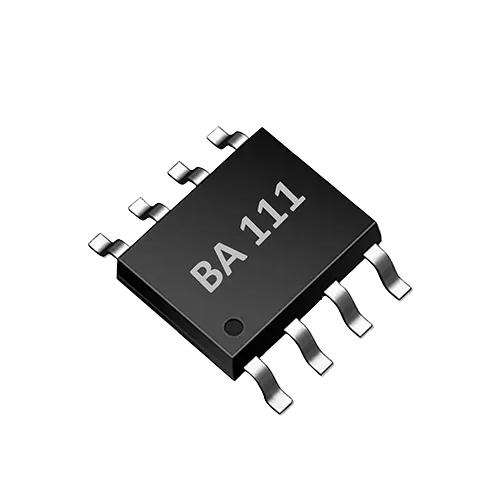
TDS sensor ICs are now widely used in water dispensers, filter life assessment for water purifiers, pet water fountains and smart home water quality displays. The BA111 is a single-channel TDS sensor interface ASIC that integrates TDS and water temperature measurement, supports bipolar probe drive and UART control, and has a nominal range of 0–3000 ppm. For engineering teams, this type of chip can significantly reduce the design effort for the analog front end and temperature compensation circuitry, but several system-level risk points still need to be confirmed during the concept phase.
This article builds a checklist around the integration of the BA111 in two scenarios—drinking water and purification, and smart appliances—across nine dimensions: target range, probe matching, power supply, temperature, UART, display, calibration, water-use scenarios and production testing. All parameter confirmations must be based on the latest datasheet; this article only provides an engineering judgment framework and does not replace the datasheet.
2. Design Checklist at a Glance
| Check Category | Core Question | Design Verification Method |
|---|---|---|
| Target Range | Does the water being measured fall within 0–3000 ppm? | Use standard solutions to cover low, mid and high ranges and check linearity |
| Probe Matching | Do the probe constant, materials and cable affect measurement? | Measure a known conductivity standard solution and observe stabilization time |
| Power Integrity | Do power supply ripple and ground bounce introduce noise? | Observe measurement fluctuation with an oscilloscope and add filtering if necessary |
| Temperature Correction | Is the temperature sensor well thermally coupled to the water quality probe? | Verify correction effectiveness in standard solutions at 25°C and 40°C |
| UART Communication | Are initialization, reading and exception recovery reliable? | Run long-duration communication stress tests and check for packet loss and timeouts |
| Display Output | Is the displayed value temperature-compensated and is the unit indicated? | Compare in parallel with laboratory methods to confirm readings are reasonable |
| Calibration Method | Do calibration points cover the operating range? | Calibrate with at least two traceable standard solutions and record deviations |
| Production Consistency | Does every unit meet the same PPM deviation requirement? | Test with standard solutions and analyze the distribution of key parameters |
3. Target Range and Measurement Span Checks
The BA111 has a TDS measurement range of 0–3000 ppm. This range is generally sufficient for common water qualities such as municipal tap water, household water purifier output and pet drinking water; typical drinking water TDS is below 1000 ppm. However, the target water quality range of the product must be defined before design: if the application involves high-salinity well water, concentrated water or industrial process water, 3000 ppm may not cover it, and an alternative solution or external dilution/range-switching mechanism is required.
Also note that the conversion factor between TDS and electrical conductivity (EC) is not a fixed constant; it is usually related to the dissolved salt composition, with an empirical value of approximately 0.5–0.7. It is recommended to record the chosen factor in the design documentation and indicate the calibration solution type on the display interface, so that users do not mistake field readings for laboratory analysis results.
4. Probe Matching and Electrode Design
The BA111 uses bipolar probe drive, which effectively reduces electrode polarization during measurement—an important characteristic for long-term online monitoring. However, the chip itself does not include electrodes; the probe must still be selected by the system designer:
- Electrode constant: should match the expected conductivity range; it is recommended to evaluate the conductivity interval corresponding to the target TDS before selecting;
- Electrode material: common materials such as stainless steel, graphite and platinum black each have advantages and disadvantages; long-term immersion scaling and cleaning difficulty must be considered;
- Cable and parasitic capacitance: excessively long probe cables introduce additional capacitance, which may affect measurement stability and response time; keep them as short as possible or use shielded cable;
- Installation location: the probe should be kept away from vibration sources such as heaters and pumps and from strong electromagnetic interference sources, while ensuring uniform water flow across the electrode surface.
It is recommended to compare at least two probes with different electrode constants during the engineering prototype stage, recording temperature drift and long-term drift as the basis for production selection.
5. Power Supply and Power Integrity
As an analog measurement device, the BA111 is relatively sensitive to power supply ripple and ground bounce. The specific supply voltage range and decoupling requirements of the chip are subject to the datasheet; during design, focus on checking:
- Whether the analog supply and digital supply are separated and whether the analog ground is connected at a single point;
- Whether ground bounce causes measurement value jumps at the instant high-current loads (such as pumps, motors and heaters) start;
- Whether probe signal routing is kept away from switching power supplies and digital signal lines.
If the system allows, some unnecessary peripherals can be turned off when UART reading is idle to reduce dynamic noise. Production testing should include power interference tests, for example continuously reading values during load switching to observe whether fluctuation is within an acceptable range.
6. Temperature Measurement and Correction
The BA111 integrates water temperature measurement and supports TDS temperature correction. Conductivity changes significantly with temperature and is usually referenced to 25°C, so the accuracy of temperature compensation directly affects the credibility of TDS readings. Design checkpoints include:
- Whether the temperature sensor (NTC, PT or integrated in the chip) is in the same location as the water quality probe or well thermally coupled;
- Whether the calibration process covers the actual operating temperature range of the product, for example 5–55°C;
- Whether the temperature response time matches the TDS measurement cycle to avoid compensation lag during rapid temperature changes.
It is recommended to verify the consistency of compensated readings with the same standard solution at different temperatures and record the deviation curve.
7. UART Communication and Host Interaction
The BA111 is controlled and read via UART. The actual baud rate, data bits, stop bits, parity mode and register map must be implemented strictly according to the datasheet. Common design issues include:
- Sending configuration commands after power-up without waiting for the chip to be ready;
- Incorrectly judging the measurement completion flag, resulting in reading stale data;
- No retry mechanism for communication timeouts and parity errors, causing the display to freeze or show incorrect values.
It is recommended that the host implement a state machine: power-up initialization → send measurement command → wait for busy flag to clear → read TDS and temperature data → verify → update display. A watchdog should also be added to prevent the entire system from becoming unresponsive during communication anomalies.
8. Display and Human-Machine Interface
In drinking water and smart appliances, TDS readings are usually presented directly to users. Display design should note:
- Clearly indicate the unit (ppm or mg/L) and whether temperature compensation has been applied;
- If the product is only used for on-site screening, conclusive wording such as "pass/fail" should not be displayed; instead use "excellent/good/fair" or maintenance recommendations;
- When setting threshold reminders (such as filter replacement), base them on multiple field measurements and laboratory comparisons, not on a single TDS value alone.
It is recommended to explain the measurement principle and limitations on the display interface or in the manual, so users do not confuse field readings with compliance testing.
9. Calibration and Verification Methods
The BA111 has a range of 0–3000 ppm; for production or prototype verification, at least two-point calibration is recommended:
- Low point: deionized water or a low-TDS standard solution to verify the zero point and low range;
- High point: a standard solution close to the upper operating limit, such as 1000 ppm or 3000 ppm, to verify range and linearity.
Standard solutions should be traceable, and the batch and expiry date should be recorded in the calibration documentation. During verification, note:
- The temperature should be stable at 25°C or temperature correction should be enabled;
- The calibration solution should fully cover the electrode and air bubbles should be removed;
- Record readings only after they stabilize; avoid taking only instantaneous values.
Laboratory comparison is only for evaluating the deviation trend of field devices and cannot replace compliance testing performed according to standard methods.
10. Suitability for Water-Use Scenarios
The BA111 is suitable for low-conductivity water scenarios such as drinking water and purification, and smart appliances. These specifically include:
- TDS display and filter life assessment for water dispenser and water purifier output;
- Water quality trend monitoring for pet water fountains, humidifiers and similar devices;
- Nodes in smart homes that need to report water-quality status over a network.
Out-of-scope boundaries: high-salinity, oil-containing, strongly acidic or alkaline, organic-solvent liquids, or liquids with unclear chemical compatibility. If the target liquid may corrode the electrodes or contaminate the measurement chamber, the materials and structure should be re-evaluated.
11. Production testing and consistency
To control the measurement consistency of each device, production testing should include the following items:
- Standard solution test: using the same batch of standard solution, record the TDS reading and temperature reading for each device and calculate the deviation;
- Calibration data writing: if the host controller supports storing calibration coefficients, they must be written on the production line and verified by read-back;
- Probe consistency: perform sampling inspection or full inspection on incoming probes and record the distribution of electrode constants;
- Aging test: short-time immersion and continuous measurement to observe whether drift exceeds tolerance.
Production test data should be retained to facilitate subsequent traceability and process improvement.
12. Limitations and boundaries
The BA111 is a TDS sensor IC, not a complete compliant water-quality analyzer. Its core value lies in simplifying the analog front end and temperature-compensation design, making it suitable for rapid on-site screening and trend monitoring. Designers need to be clear about the following:
- 0–3000 ppm is the IC's nominal range; the actual measurable range is also affected by the probe, cable and PCB layout;
- On-site TDS readings may deviate from laboratory chemical analysis results and must not be used for compliance determination;
- All specific electrical parameters, UART protocol and pin definitions are subject to the latest BA111 datasheet.
13. FAQ
Q1: How does a TDS sensor work? A1: A TDS sensor essentially measures the electrical conductivity (EC) of water and then converts it to TDS using an empirical coefficient. The BA111 uses bipolar drive to reduce electrode polarization and integrates temperature correction, so that readings are closer to the equivalent value at a 25°C reference.
Q2: Can the BA111 measure pure water? A2: Pure water has extremely low conductivity and is difficult to measure. Whether it is suitable depends on the probe constant, circuit noise and the lower limit of the range. Refer to the datasheet and verify by actual measurement with deionized water.
Q3: Does UART support a multi-slave bus? A3: The BA111 is a single-channel TDS sensor interface, and UART is mainly used for control and data reading of a single IC. Whether multi-slave cascading or address configuration is supported must be based on the datasheet description.
Q4: What is the difference between on-site TDS measurement and laboratory testing? A4: On-site TDS measurement is usually used for rapid screening, trend monitoring and equipment control; it responds quickly but has limited accuracy and selectivity. Laboratory testing is carried out according to standard methods, and its results have compliance validity. The two cannot substitute for each other.
Discuss your application
Tell us your target parameters, water matrix, interface and annual volume. Our engineering team will recommend a practical configuration.
Request a Quote