
# How an EC Measurement IC Reduces TDS Probe Polarization: BA111 Bipolar Drive Explained
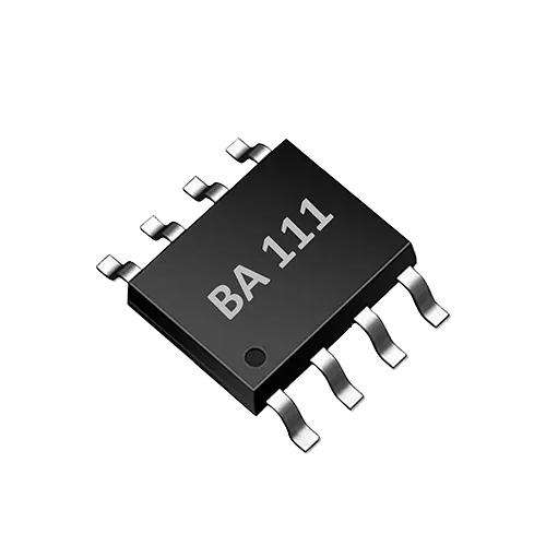
TDS (total dissolved solids) sensors are commonly used to monitor outlet water quality in water purifiers, water dispensers and smart appliances. Field devices have limited space and short maintenance windows, so designs usually favor highly integrated TDS sensor ICs. The BA111 is a single-channel TDS sensor interface ASIC with a typical range of 0–3000 ppm, integrated TDS temperature correction, UART control, and bipolar probe drive that reduces polarization effects, with very few external components. Starting from the mechanism of probe polarization, this article explains why bipolar drive matters and emphasizes that the probe, circuit, temperature and complete-system calibration still need to be verified together.
How a TDS sensor works: why the probe polarizes
TDS is not a direct measurement of the total mass of solid particles; it is derived by measuring the conductivity of the water sample and converting it to a TDS reading using an empirical coefficient. The more dissolved ions present, the higher the conductivity, so with fixed electrode geometry and excitation conditions, ion concentration can be estimated from the current/voltage relationship. A typical TDS probe consists of two electrodes; after immersion in the water sample, AC or DC excitation is applied and the loop current is measured.
With DC excitation, oxidation-reduction and ion migration occur continuously at the electrode surfaces, with positive and negative ions accumulating at the two electrodes respectively to form a back EMF; at the same time, bubbles or deposits may form on the electrode surfaces, changing the effective electrode area and interfacial impedance. This polarization effect causes the reading to drift over time, especially at high conductivity or during long-term continuous monitoring. In addition, changes in the electrode surface condition alter the cell constant, further affecting TDS conversion accuracy.
Bipolar drive periodically reverses the electrode polarity so that each electrode alternately acts as anode and cathode, thereby avoiding one-directional ion accumulation and electrode corrosion. The net electrochemical reaction is close to zero, and concentration polarization and electrode deposition are significantly suppressed. The table below compares the typical differences between the two drive methods:
| Drive method | Polarization behavior | Long-term stability | System complexity |
|---|---|---|---|
| DC/unipolar drive | One-directional ion migration, prone to concentration polarization and electrode deposition | Noticeable reading drift, requiring frequent cleaning | Simple drive circuit, but high maintenance cost |
| Bipolar AC drive | Electrode polarity periodically reversed, net polarization effect significantly reduced | Less drift, suitable for long-term online monitoring | Requires timing control, but can be integrated in the ASIC |
BA111 as an EC measurement IC: how bipolar drive suppresses polarization
The BA111 integrates a bipolar probe drive circuit internally, so developers do not need to build an external H-bridge or precision timing circuit. The chip alternately changes the excitation direction between the two electrodes at a certain frequency, operating the probe in AC mode and reducing the impact of polarization on measurement at the source.
In addition to bipolar drive, the BA111 as an EC measurement IC integrates the following functions in a single ASIC:
- 0–3000 ppm TDS range: covers the common TDS range of drinking water, water purifier product water and smart appliance water, but is not suitable for high-salinity water.
- TDS temperature correction: water temperature changes significantly affect conductivity; on-chip correction reduces the software compensation work required later.
- UART control: digital interface output is more interference-resistant than analog voltage output and facilitates direct communication with the MCU.
- Single-channel measurement: suitable for a standalone TDS probe or single-point monitoring, with a simple external circuit.
- Very few external components: reduces BOM cost and PCB footprint, supporting miniaturized designs.
For engineers, the value of bipolar drive lies not only in reducing polarization but also in improving consistency during long-term operation. Functions such as water purifier filter life reminders and water dispenser water quality displays require the sensor to maintain a stable trend output over weeks or even months, rather than laboratory-grade absolute accuracy. The BA111's bipolar design makes this trend monitoring more reliable.
Why complete-system verification cannot be skipped: the combined effect of probe, circuit, temperature and calibration
Although the BA111 solves the timing problem of polarization drive at the chip level, the accuracy of the final TDS reading still depends on the coordination of the probe, PCB routing, temperature sensor mounting and complete-system calibration.
Probe selection and aging: different electrode materials (such as graphite, stainless steel and platinum) and geometries change the cell constant and polarization characteristics. Bipolar drive reduces polarization but cannot eliminate contamination, scale or biofilm on the probe surface. After long-term immersion, even if the chip drive is functioning normally, changes in probe surface impedance will still cause deviations, so periodic cleaning or replacement is required.
Circuit layout: TDS probe signals are usually small currents or voltages and are susceptible to digital circuits, switching power supplies and ground noise. Although the BA111's digital UART interface reduces long-distance transmission of analog signals, PCB layout still requires attention: keep analog probe traces as short as possible and away from high-frequency switching nodes; maintain a complete ground plane; place decoupling capacitors close to the power pins. Refer to the layout recommendations in the BA111 datasheet to avoid measurement offsets caused by parasitic capacitance or leakage current.
Joint verification of temperature correction: the TDS temperature correction function needs to know the actual water temperature. If the temperature sensor is far from the probe or mounted on the PCB, the measured temperature may differ from the water sample temperature due to a gradient. In the complete-system design, ensure good thermal contact between the temperature sensor and the measured water body, and verify the correction effect over the target temperature range. The BA111's temperature correction coefficients are usually preset in the chip, but different water samples or probe combinations may require fine-tuning, which should be confirmed during complete-system calibration.
Complete-system calibration: the probe, cable, connector and housing all introduce additional series impedance or parallel capacitance. Calibrating the chip or probe alone in the laboratory does not represent the performance of the complete system in its final installed state. Use standard TDS/conductivity solutions to perform two-point or three-point calibration after final assembly, and store the calibration coefficients in the MCU.
Selection and implementation steps: from schematic to batch verification
The following steps can serve as a reference process for engineers designing a TDS monitoring subsystem with the BA111:
- Confirm the application range and water quality type: the BA111's 0–3000 ppm range is suitable for drinking water, water purifiers and general appliance water. If the water TDS exceeds 3000 ppm or contains large amounts of oil, grease or suspended solids, evaluate the risks of probe contamination and range overflow.
- Probe matching and selection: choose a TDS probe whose cell constant and electrode material are suitable for bipolar AC excitation; the probe should have good linearity over the 0–3000 ppm range and withstand long-term immersion. Confirm polarization recovery characteristics with the probe supplier.
- Hardware design: complete the schematic according to the BA111 datasheet, matching the UART interface to the MCU level; keep analog input traces short and wide, away from interference sources; ensure adequate power supply decoupling.
- Temperature sensor mounting: place the temperature sensing element close to the water flow or probe cavity, and avoid mounting it near heat-generating components; perform thermal insulation or thermal equilibrium verification if necessary.
- Complete-system calibration: use at least two standard solutions covering the working range (for example, near 0 ppm and near the target TDS value), and calibrate with the final housing and wiring in place. Record the relationship between raw readings and standard values to determine the linear correction parameters.
- Temperature cycling verification: test the temperature-corrected TDS reading at different water temperatures (such as 5°C, 25°C and 45°C) and confirm that the deviation is within an acceptable range.
- Long-term immersion and drift testing: immerse the complete system continuously in a representative water sample, record the reading drift over 7 days or longer, and evaluate the cleaning cycle and sensor maintenance strategy.
It should be clearly understood that the BA111 output is suitable as a field screening, trend monitoring and appliance control signal, and should not be used as a basis for compliance testing against drinking water standards or regulations. The latter requires certified laboratory methods and calibrated instruments, and usually requires more complex sample preparation and quality control processes.
Limitations and application boundaries
- Range limitation: 0–3000 ppm TDS does not cover seawater, industrial high-salinity wastewater or certain concentrates; beyond this range, dilution or a sensor with a different range is required.
- Bipolar drive is not a cure-all: it significantly reduces electrode polarization but cannot completely eliminate drift caused by probe contamination, scale, biofilm or electrode aging.
- Influence of the TDS conversion coefficient: the TDS value is obtained by multiplying conductivity by an empirical conversion coefficient, and water samples with different ion compositions correspond to different coefficients. The BA111 output uses a certain default coefficient for TDS; if the ion composition of the water sample differs greatly from the calibration water, the absolute TDS reading may deviate from laboratory gravimetric results.
- Assumptions of temperature correction: the on-chip temperature compensation is based on typical aqueous solution characteristics; under extreme water temperatures, rapid temperature changes or unusual water quality, the residual error after compensation still needs to be evaluated by measurement.
- Not a laboratory analytical instrument: the BA111 is not a certified analytical instrument and should not be used to issue water quality reports requiring legal validity.
FAQ
Q: As an EC measurement IC, can the BA111's bipolar drive completely eliminate probe polarization?
A: It cannot completely eliminate it, but by periodically reversing electrode polarity, the net electrochemical reaction can be brought close to zero, significantly reducing drift caused by concentration polarization and electrode deposition. The actual effect also depends on probe material, surface condition and water quality.
Q: How does a TDS sensor work?
A: A TDS sensor indirectly estimates total dissolved solids by measuring the conductivity of the water sample. After excitation is applied to the probe electrodes, dissolved ions conduct electricity to form a current; the chip measures this current and converts it to a TDS value. Temperature correction is used to eliminate the effect of temperature on conductivity.
Q: Can the BA111 be used directly for drinking water compliance testing?
A: Not recommended. The BA111's 0–3000 ppm output is suitable for field screening, trend monitoring and appliance control, and is not a certified laboratory analytical method. Compliance testing should be performed by qualified laboratories using standard methods.
Discuss your application
Tell us your target parameters, water matrix, interface and annual volume. Our engineering team will recommend a practical configuration.
Request a Quote