
# How to Use the BA111 in Countertop and Under-Sink Water Purifiers: TDS Sensor IC Design Essentials
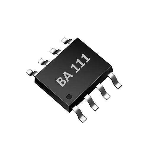
In countertop instant-heating water purifiers and under-sink purifiers, the TDS value is an important reference that helps users quickly understand changes in water quality and filter life. The BA111 is a single-channel TDS sensor IC that integrates bipolar probe drive, TDS temperature correction and UART control, enabling 0–3000 ppm TDS detection with only a few external components. This article is aimed at hardware engineers, system integrators and technical buyers, and discusses product design approaches, display strategies and maintenance prompts for countertop and under-sink water purifiers.
How a TDS sensor IC works: conductivity, temperature compensation and the BA111 measurement chain
A TDS sensor IC typically calculates TDS indirectly by measuring the conductivity of water. The more dissolved ions in the water, the higher the conductivity; the IC applies an alternating excitation between two electrodes, detects the current response, and then converts it to ppm using a built-in temperature compensation algorithm. The BA111 uses bipolar drive, which reduces probe polarization and suits long-term continuous monitoring. As an EC measurement IC, it integrates the analog front end, excitation source and digital interface, outputting measurement results over UART so the host MCU needs no complex analog conditioning.
Key point: TDS does not directly measure all dissolved substances; it relies on conductivity conversion. The conversion factor may differ between water types (e.g., proportions of sodium salts versus calcium and magnesium salts), so this value is better suited for trend monitoring and filter comparison on the same device rather than as an absolute laboratory result.
Countertop purifiers: fast display and user interaction
Countertop purifiers usually have a dedicated panel that can display raw-water TDS, purified-water TDS, or remaining filter percentage in real time. The single-channel nature of the BA111 makes it suitable for deployment in the following locations:
- Raw-water side: display inlet TDS to help users understand local water quality.
- Purified-water side: display outlet TDS to reflect the removal performance of the RO membrane or composite filter.
- Bypass measuring cup: manual water sampling for measurement, convenient for cleaning and maintenance.
Because the BA111 outputs digital results over UART, the panel MCU can read them directly and drive a segment display or color screen without an additional ADC. Design notes:
- Install the probe in a low-flow area to prevent bubble attachment.
- The temperature sensor should be in the same water chamber as the probe to ensure effective temperature compensation.
- Keep UART communication lines away from pumps and heaters to reduce electromagnetic interference.
- Keep probe connection wires as short as possible, and add ESD protection and common-mode filtering at the PCB entry.
Under-sink purifiers: integration space and maintenance accessibility
Under-sink purifiers are installed below the sink, where space is tight and maintenance frequency is lower. Here, sensor installation and probe life are more critical:
- Prefer a flow cell with quick connectors, inserting the probe into the main water path or a bypass.
- If water flow stagnates for long periods, periodic automatic flushing or brief excitation is recommended to suppress biofilm.
- Under-sink purifiers often have only a faucet light ring or a simple digital screen, so TDS can be mapped to a filter-life status light rather than showing a specific value.
The BA111's small package and minimal external circuitry allow it to be mounted directly on a sensor board close to the water path, reducing noise introduced by long cables. Note, however: if the control board is far from the probe, the UART signal should use shielded cable or RS-232 level conversion to avoid water stains and motor interference.
The table below compares the design priorities of the two product types:
| Design dimension | Countertop purifier | Under-sink purifier |
|---|---|---|
| Installation location | Panel bypass or removable measuring cup | Main line or branch flow cell |
| Display method | Segment/color screen showing TDS ppm directly | Status light, faucet digital ring or Bluetooth |
| Maintenance accessibility | Users can clean the probe periodically | Requires tools or quick connectors; longer maintenance intervals |
| Interference focus | Common-mode noise from pumps and heaters | Long cables, humid environment |
| Temperature compensation | NTC built into the water chamber or inside the IC | NTC near the probe to prevent pipe-wall temperature deviation |
Selection and verification: from lab to field
When selecting for a project, it is advisable to confirm the following questions:
- Is the water-quality range within 0–3000 ppm? If raw-water TDS may exceed 3000 ppm, dilution or a multi-range approach is needed.
- Is only a single channel needed? If both inlet and outlet must be monitored simultaneously, two BA111 devices may be needed, or a multi-channel approach.
- Does the host support UART? If an idle UART is available, the BA111 can reduce BOM cost.
- Are the probe material and structure compatible with bipolar drive? Stainless steel or graphite electrodes both work, but prolonged DC bias should be avoided.
Verification is carried out at three levels:
- Laboratory calibration: use standard solutions of known conductivity (e.g., KCl) to plot a conductivity–TDS curve and verify the deviation of the IC output from the nominal value.
- Whole-machine testing: feed water sources of different TDS into the purifier's actual water path, record the time from startup to a stable reading, and check for reading jumps during sudden temperature changes (e.g., when the heater turns on).
- Long-term aging: simulate end-of-filter-life conditions, scale deposits and probe contamination to confirm that reading trends are reasonable. Note that such tests are field screening or trend monitoring and cannot replace regulatory testing by a third-party laboratory.
Example implementation steps
In a specific project, the following steps can be used as a reference:
- Confirm water level and flow rate, and choose a flow cell or measuring cup.
- Connect the BA111 probe drive terminals to the two-electrode probe, keeping wire length as short as possible and ensuring waterproof sealing.
- Configure UART parameters according to the datasheet, and have the host parse the ppm and temperature data.
- After power-up, first perform a zero check with deionized water, then do a single-point or two-point calibration with a known TDS solution.
- Run a temperature cycling test to confirm that temperature compensation is effective and the reading does not drift noticeably.
- Run a long-term operation test to observe probe scaling and reading drift, and determine the maintenance interval.
Limitations and engineering boundaries
The BA111 provides single-point, single-channel TDS trend data, not a compliance determination of water quality. It cannot distinguish between types of dissolved solids, nor can it detect microorganisms, residual chlorine, heavy metals or organic pollutants. Its ppm reading is affected by temperature, ion composition and probe aging, so cross-device comparisons should be made with caution.
In addition, although the UART output simplifies the interface, non-isolated probe excitation may couple through the water medium to other sensors, so ground isolation and filtering should be handled carefully in the PCB layout. If the product needs to connect to a municipal water supply network or claim "safe for direct drinking," independent third-party testing according to local standards is mandatory.
FAQ
Q: How does a TDS sensor IC work, and why is temperature compensation needed? A: A TDS sensor IC obtains TDS indirectly through conductivity measurement. The conductivity of water increases as temperature rises, so an internal or external NTC samples the water temperature and corrects the reading, making the ppm value more stable as temperature changes. The BA111 has built-in TDS temperature correction, simplifying system design.
Q: What could cause an unstable outlet TDS reading in an under-sink purifier? A: Common causes include bubbles, flow fluctuations caused by pump start/stop, scaling or biofilm on the probe surface, and a temperature compensation sensor that is not synchronized with the probe. It is advisable to check flow-cell venting, add software filtering, and clean or automatically flush the probe periodically.
Q: Is the BA111 suitable for measuring both inlet and outlet water at the same time? A: The BA111 is a single-channel TDS sensor IC, and each IC can measure only one measurement point. If both raw water and purified water must be monitored simultaneously, two BA111 devices can be used to measure them separately, with the host aggregating and comparing the results.
Discuss your application
Tell us your target parameters, water matrix, interface and annual volume. Our engineering team will recommend a practical configuration.
Request a Quote