
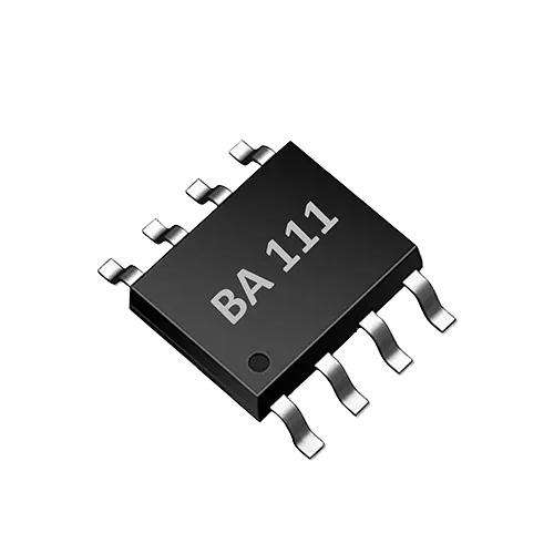
When OEM teams adopt a TDS sensor IC such as the BA111 for water appliances or smart water-using devices, the most common failure is not a software bug but a failure to align hardware boundaries and firmware control logic before requesting a quote. The BA111 is a single-channel TDS and water-temperature measurement ASIC with integrated bipolar probe drive and UART control, suited to scenarios that require miniaturization and a low external component count; however, pre-purchase technical confirmation directly determines first-pass success of the prototype and mass-production maintenance cost.
It should be clear: an IC like the BA111 is intended for on-site rapid screening, trend monitoring and device control, and is not equivalent to laboratory water-quality analysis. Drinking-water compliance determination, discharge monitoring or arbitration testing must be performed by a qualified laboratory using standard methods. This article builds a pre-purchase verification checklist solely on verified product facts and does not invent unconfirmed parameters, certifications or test results.
Why Hardware and Firmware Boundaries Must Be Confirmed Before Sourcing a TDS Sensor IC
TDS is generally not a directly measured physical quantity but an estimate derived from the conductivity of the solution. Known capabilities of the BA111 include 0–3000 ppm TDS measurement, TDS temperature correction, single-channel measurement, bipolar drive to reduce probe polarization, and very few external components. These facts indicate that it targets highly integrated single-point measurement nodes, but it cannot cover every water-quality scenario. Before purchase, the following questions must be closed out one by one:
- Is the TDS peak of the target water quality within the 0–3000 ppm range over the long term?
- Does the system need to measure multiple independent channels simultaneously?
- How long is the connection between the on-site probe and the IC, what is the cable capacitance, and what is the ESD risk?
- Does the MCU have sufficient UART resources and real-time response capability?
- Can the annual mass-production volume support ASIC supply and package selection?
Exposing these questions early is far more cost-effective than changing the analog front end or rewriting the driver after SMT assembly.
1. Confirming Range and Measurement Target
The verified range of the BA111 is 0–3000 ppm TDS. For typical scenarios such as drinking water, water purifier outlet and pet water fountains, this range is usually sufficient; however, boiler blowdown, concentrate or high-salinity process water may exceed the range. Before purchase, confirm:
- What are the normal range and maximum peak of TDS in actual use?
- Should more than 20% range headroom be reserved to account for sensor aging or temperature effects?
- If the range is occasionally exceeded, does the IC saturate its output, report an error, or require external protection?
- Is the target parameter TDS or conductivity? If EC is ultimately displayed, the conversion factor and temperature compensation reference must be specified.
2. Power Supply and Power Consumption Boundaries
The BA111 is described as having "very few external components", but parameters such as voltage range, operating current, sleep current and power-up sequencing in the datasheet must be confirmed at the schematic stage. It is advisable to request the following information from the manufacturer or distributor:
- Recommended supply voltage and allowable fluctuation range;
- Current consumption in continuous measurement and standby modes;
- Whether an external LDO, decoupling capacitor or reset circuit is required;
- Power-up stabilization time and the wait period for the first valid output.
If the product is a battery-powered portable device or pet appliance, power consumption directly affects battery life, so a power budget must be provided before requesting a quote.
3. Probe and Analog Front End
Bipolar drive is a key feature of the BA111 for reducing probe polarization. Long-term DC excitation may generate a polarization layer on the electrode surface, causing reading drift; bipolar drive mitigates this by alternating excitation. However, this does not mean all probes can be connected directly. Before purchase, confirm:
- Recommended cell constant (e.g., K=0.1, 1.0 or 10) and electrode plate material;
- Maximum probe cable length and the effect of cable capacitance on measurement accuracy;
- Whether an external divider resistor, filter capacitor or protection diode is required;
- How to protect the IC input pins under on-site ESD, humidity and condensation conditions.
4. UART Communication and Firmware Integration
The BA111 provides a UART control interface, meaning the MCU can read measurement results or configure operating states via serial commands. On the firmware side, confirm:
- Default baud rate, data bits, stop bits and parity;
- Command frame format: whether there are start/stop bytes, length fields and checksums;
- Measurement result refresh rate and whether single or continuous conversion is supported;
- Exception recovery mechanism: how to reset after communication timeout, error frames or a hung bus;
- Whether official reference drivers, register descriptions or state-machine examples are provided.
It is advisable to write a UART test script before purchase and capture real timing with a logic analyzer, so that command incompatibility is not discovered only during full-system integration testing.
5. Temperature Measurement and Compensation
The BA111 integrates TDS temperature correction, an important function for ensuring reading consistency at different water temperatures. But is the temperature sensor integrated inside the IC, or does it require an external NTC or digital temperature sensor? Does the compensation algorithm use fixed coefficients or configurable ones? These must be confirmed before the hardware design is finalized:
- Temperature measurement range and response time;
- Whether temperature compensation is automatic or requires MCU configuration;
- Whether the compensation reference temperature is 25°C or another temperature;
- Whether temperature compensation can be disabled for raw-data verification.
If the product operates at different water temperatures, TDS readings at high and low temperature points must be measured to confirm compensation consistency.
6. Calibration and Metrological Traceability
Any TDS measurement system needs to be calibrated with standard solutions. As a measurement front end, the BA111 cannot automatically guarantee that the final reading conforms to a given standard. Before purchase, clarify:
- Whether the IC is internally calibrated at the factory;
- Whether on-site calibration uses a single-point or two-point scheme;
- Recommended standard solution concentrations and calibration procedure;
- Whether calibration data is stored on the MCU side or in non-volatile memory inside the IC;
- How often recalibration is needed and the acceptable range of calibration drift.
To reiterate: an on-site TDS sensor is used for trend assessment and rough screening and cannot replace laboratory analysis. If product marketing involves compliance or health claims, these must be supported by laboratory data, not by IC readings alone.
7. Annual Volume, Package and Supply
The BA111 is an ASIC device, so commercial and supply boundaries must be confirmed with the supplier before purchase:
- Estimated annual volume and minimum order quantity;
- Available packages, pin pitch and RoHS/REACH status;
- Tape-and-reel packaging, MSL level and reflow soldering requirements;
- Lead time, safety stock and risk of alternative devices.
If annual volume is small, evaluate the long-term supply stability of the ASIC and whether it is worth designing for a single source.
8. Sample Validation and Boundary Testing
Before bulk purchasing, small-batch sample validation must be completed. A suggested test plan should include at least:
- Covering low, middle and high points of the range with multiple standard solutions;
- High- and low-temperature testing to verify temperature compensation;
- Long-term continuous operation to observe reading drift and polarization recovery;
- UART communication stress testing, including interruptions, reconnections and error frames;
- Post-assembly testing in the actual product enclosure to confirm probe sealing and cable effects.
Only samples that pass boundary testing can proceed to small-batch trial production.
9. Documentation and Support
Before purchase, request a complete technical documentation package from the supplier, including at least:
- Datasheet, pin definitions and absolute maximum ratings;
- Reference schematic and BOM recommendations;
- Application notes: probe selection, temperature compensation, calibration procedure;
- Firmware communication protocol and sample code;
- Reliability data or quality reports (if already available).
If a parameter is missing from the documentation, do not guess — confirm it in writing.
Purchasing Decision Checklist
| Checklist Item | Questions to Confirm with the Manufacturer | BA111 Verified Information | Key Engineering Considerations |
|---|---|---|---|
| Measurement Range | Is the target water TDS peak ≤ 3000 ppm? | 0–3000 ppm TDS measurement | Keep 20% headroom; if over range, dilute the sample or change the design |
| Probe Drive | Which cell constant and electrode plate material are suitable? What are the cable constraints? | Bipolar drive reduces polarization | Avoid continuous DC excitation, which causes measurement drift |
| Temperature compensation | Built-in or external temperature sensor? Is the compensation algorithm configurable? | Supports TDS temperature correction | Verify compensation consistency at measured high and low temperature points |
| Communication | UART default parameters, command frames, and error recovery? | UART control | Add timeout, checksum, and re-read mechanisms |
| Power Supply | Operating/sleep current and power-up timing? | Minimal external components | Design decoupling and reset per the datasheet |
| Calibration | Factory calibration? On-site single-point/two-point options? | Standard solutions required | Define on-site calibration frequency and record-keeping method |
| Mass Production | Annual volume/packaging/lead time? | ASIC device | Lock in packaging and alternative-part validation early |
Frequently Asked Questions
Is the BA111 a TDS sensor IC or an EC measurement IC?
The BA111 database describes it as a single-channel TDS and water temperature measurement ASIC with 0–3000 ppm TDS measurement and temperature correction. TDS is typically derived from electrical conductivity (EC), but the BA111 is positioned as an integrated TDS measurement front end, not a general-purpose EC analyzer.
How does a TDS sensor work?
Dissolved salts in water increase the solution's conductivity. A TDS sensor applies an AC or polarity-alternating signal through electrodes, measures the solution's conductivity, and then estimates the TDS value using an empirical coefficient. The BA111 uses bipolar drive to reduce the effect of probe polarization on readings and applies temperature correction to reduce errors caused by water temperature changes.
Can the BA111 be used for drinking water compliance testing?
It cannot be used alone for compliance testing. The BA111 is suitable for in-device trend monitoring, filter life reminders, and rough screening. Drinking water safety determinations must be performed by a qualified laboratory using national standard methods; a sensor IC can only serve as a supplementary warning tool.
Discuss your application
Tell us your target parameters, water matrix, interface and annual volume. Our engineering team will recommend a practical configuration.
Request a Quote