
Why a TDS sensor IC needs probe matching verification
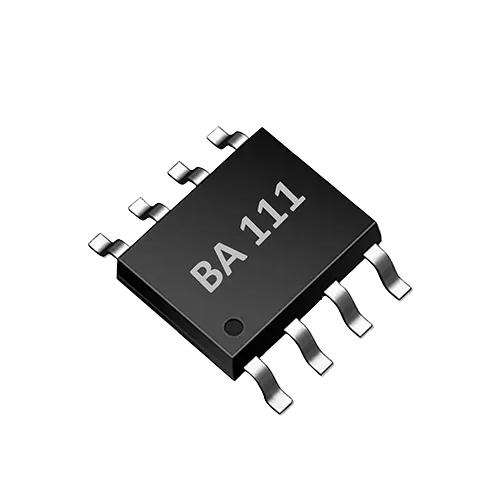
The BA111 is a single-channel TDS sensor interface ASIC that integrates bipolar probe drive, TDS temperature compensation, and UART control, with a range of 0–3000 ppm. The IC targets applications such as smart appliances and can simplify water-quality measurement electronics. But the BA111 is not a complete measuring instrument on its own: it requires an external TDS or conductivity probe, and the probe constant, temperature compensation, and sample characteristics must be incorporated into system calibration. If matching verification is skipped, a finished product may read correctly in standard solution but deviate significantly with real water samples or in volume production. Matching verification should therefore span development, pilot runs, and production screening, covering probe constant, water sample, temperature, calibration points, repeatability, production-line consistency, and abnormal samples.
Probe constant: the baseline parameter for matching verification
TDS measurement typically measures conductivity first, then converts to TDS (ppm) using an empirical factor. The probe constant K (cm⁻¹) describes the geometric relationship between the two electrodes and is the conversion factor between conductivity and conductance. As an EC measurement IC, the BA111 provides bipolar excitation to the probe and acquires the response signal, but the probe constant must be calculated externally by the host MCU or a host computer based on measurement results and standard solutions. During matching verification, first back-calculate the probe constant using standard solutions of known conductivity and confirm it matches the nominal value; if the deviation exceeds the system's allowable tolerance, the probe must be adjusted or replaced. Bipolar drive helps reduce probe polarization and lowers the risk of electrolysis and scaling caused by long-term DC bias, making the calibrated constant more stable across repeated measurements.
Water sample and temperature: a repeatable verification environment
The choice of water sample directly affects the reproducibility of matching verification. Use certified conductivity reference materials or freshly prepared KCl solution rather than tap water or surface water of unknown composition as the basis for development calibration. Temperature significantly affects conductivity—roughly 2% / °C near room temperature. The BA111 has TDS temperature compensation, but compensation depends on correct temperature input and algorithm matching. Record both the water sample temperature and the IC reading during verification, and evaluate at at least three representative temperature points (e.g., 15 ℃, 25 ℃, 35 ℃, depending on the application environment). During testing, avoid bubble adhesion, condensation entering connectors, direct sunlight, or localized heating.
Calibration point design: from range coverage to regression residuals
The BA111's range is 0–3000 ppm, and matching verification should cover the low, mid, and high segments as much as possible. A typical approach uses standard solutions near pure water or low concentration, near the range midpoint, and saline or standard solution near the upper range limit; the specific ppm values must be converted from standard solution conductivity and probe constant. Note that the conversion between TDS and conductivity is not linear and consistent for all salts, so multi-point regression should be performed during development to examine slope, intercept, and residuals. If the slope differs noticeably between the low-mid and mid-high segments, segmented calibration or re-evaluation of the probe constant may be needed. Production-line batch verification can be simplified, but first-time matching and design changes require re-running multi-point verification.
| Verification dimension | Key operation | Pitfall to avoid |
|---|---|---|
| Probe constant | Back-calculate K with standard solution and compare to nominal value | Relying only on the manufacturer's nominal value without verification |
| Water sample | Use certified standard solutions or KCl solution | Using tap water or unknown samples |
| Temperature | At least three temperature points, record compensated readings | Measuring only at room temperature, ignoring temperature drift |
| Calibration points | At least three-point regression across low, mid, and high | Single-point calibration then volume production |
| Repeatability | Same sample 10+ times, calculate CV | Judging from only one or two readings |
| Production-line consistency | Measure multiple combinations, set upper and lower limits | Testing only a single IC or probe |
| Abnormal samples | Screening for interference such as bubbles, oil film, or bending | Using abnormal samples to judge pass/fail |
Repeatability, production-line consistency, and abnormal samples
Repeatability verification: under the same water sample and temperature conditions, take 10 or more consecutive readings of the same combination, calculate standard deviation and coefficient of variation, and observe whether readings show monotonic drift, jumps, or increased noise. The BA111's bipolar drive and minimal external circuit design generally help reduce external interference, but this must still be confirmed with test data. Production-line consistency verification: prepare multiple probes of the same model and multiple BA111 test boards, measure combinations with one or two standard solutions, and check output distribution, range, and out-of-limit ratio; UART control on the BA111 enables automatic reading, logging, and limit checking, reducing manual recording errors. Abnormal sample verification: introduce interference conditions such as bubbles, oil film, scaling, or cable bending, and observe whether readings jump and whether recovery time is acceptable; these samples expose poor contact, shielding failure, or probe insulation damage and should not be the sole pass/fail criterion.
Matching verification implementation steps
- Prepare the BA111 test board, target TDS probe, standard conductivity solutions, thermometer/thermostatic bath, and host software.
- Measure in a mid-range standard solution, calculate the actual probe constant, and compare it with the nominal value.
- Measure the same standard solution at multiple temperature points and evaluate the consistency of temperature-compensated readings.
- Perform multi-point regression with at least three standard solutions (low, mid, high), recording slope, intercept, and residuals.
- Select a mid-range standard solution and repeat measurements 10 or more times, calculating repeatability metrics.
- Sample multiple probe and IC combinations and set upper and lower limits for rapid production-line testing.
- Add abnormal samples for interference screening and evaluate recovery characteristics.
- Produce a matching verification report including probe constant, temperature compensation coefficient, calibration point data, repeatability, and batch conclusions.
Applicable boundaries and limitations
The matching verification method described here belongs to engineering selection, production-line screening, and on-site trend monitoring, and is not equivalent to laboratory water-quality analysis or statutory testing. The BA111's output requires conversion through the probe constant and calibration model, and measurement accuracy is closely related to probe quality, cable impedance, mounting structure, and water sample composition. For real water samples with different salt compositions, use standard solutions close to the target water sample for matching verification; samples outside the BA111's 0–3000 ppm range should not be measured directly. Any certification, compliance, or accuracy claims must be tested and confirmed by the user in the target finished product.
FAQ
Q: How is the probe constant configured for the BA111 TDS sensor IC? A: The probe constant is back-calculated from standard solutions of known conductivity and used by the external host MCU when calculating TDS; the BA111 provides the measurement front end and bipolar drive, and does not automatically store or calculate the probe constant.
Q: Can matching verification replace a statutory water-quality test report? A: No. This method is for development, screening, and trend monitoring; when a statutory report is required, testing must be performed by a qualified laboratory according to the relevant standard methods.
Q: Should production lines reduce to single-point calibration? A: Single-point calibration is not recommended for first-time verification. During development, at least three points should be used to confirm linearity and residuals; after the model is established through multi-point verification, a production-line rapid station can use one or two points for limit screening.
Discuss your application
Tell us your target parameters, water matrix, interface and annual volume. Our engineering team will recommend a practical configuration.
Request a Quote