
TDS (Total Dissolved Solids) is a common parameter for measuring the total amount of dissolved inorganic salts and small amounts of organic matter in water, widely used in water dispensers, water purifiers and smart home appliances. However, TDS measurement based on the conductivity method is very sensitive to temperature: rising water temperature enhances ion mobility, causing conductivity to increase and TDS readings to be too high. Without temperature compensation, the same water sample may give significantly different results in different seasons, affecting filter life assessment and water quality display. The BA111 is a TDS sensor IC designed specifically for single-channel TDS measurement, integrating TDS and water temperature measurement functions with built-in TDS temperature correction, providing products with reliable TDS digital output normalized to 25°C. This article analyzes from an engineering perspective how the BA111 implements temperature compensation, as well as system-level verification and display limits.
Why TDS Measurement Must Include Temperature Compensation
The conductivity of water is determined jointly by ion concentration and ion mobility. When temperature rises, ion migration speeds up and conductivity increases accordingly. Experiments show that within the common drinking water temperature range, conductivity may change by about 2% for every 1°C change in water temperature. For measurement systems that convert conductivity to TDS, this means the uncompensated TDS value of the same water sample at 10°C and 30°C may differ by more than 40%. This drift is enough to cause misjudgment in water purifier filter life assessment, or to give users a wrong perception of water quality changes. Therefore, any TDS measurement solution intended for practical application must include a temperature compensation step. As a TDS sensor IC, the BA111 implements this function at the chip level, reducing the computational burden on the main control MCU and avoiding additional errors introduced by external temperature sensors.
Sensor and Water Temperature Data Coordination in the BA111 TDS Sensor IC
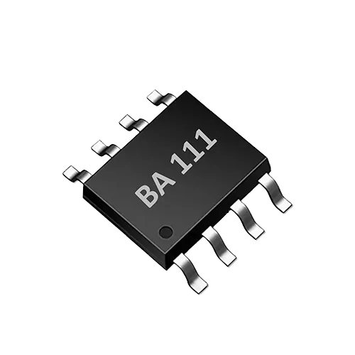
The BA111 is a highly integrated single-channel TDS sensor interface ASIC that uses bipolar probe drive to reduce probe polarization, extend probe life and improve long-term measurement stability. The chip simultaneously acquires water temperature and conductivity signals internally, and outputs temperature-compensated TDS digital values through a UART interface. For system integrators, this means that reliable TDS data can be obtained by connecting just two probe electrodes and minimal external components, without the need to design a complex analog front end and compensation algorithm independently.
The table below summarizes the key features of the BA111:
| Feature | Description |
|---|---|
| TDS measurement range | 0–3000 ppm |
| Temperature compensation | Built-in TDS temperature correction |
| Probe drive | Bipolar drive, reduces polarization |
| Communication interface | UART control |
| External circuit | Minimal external components |
In engineering terms, the BA111 implementation flow can be summarized as: the probe generates an alternating excitation signal under chip drive, measuring solution conductivity; at the same time, an on-chip temperature sensor acquires water temperature; an internal compensation algorithm converts the raw conductivity value to a TDS value at a reference temperature (typically 25°C); finally, the digital result is output via UART. This integrated approach makes the BA111 well suited for space-constrained, low-power water dispensers and smart home appliance products.
System-Level Verification Methods
To verify the effectiveness of BA111 temperature compensation, the development team should conduct multi-temperature point testing under controlled conditions. Recommended steps are as follows:
- Prepare standard solutions with known TDS values (such as potassium chloride or sodium chloride solutions), and use a calibrated laboratory conductivity meter to calibrate their reference values at 25°C.
- Place the container holding the standard solution in a constant-temperature bath, stabilizing at target temperatures such as 5°C, 15°C, 25°C, 35°C and 45°C respectively.
- Record the TDS value output by the BA111 at each temperature point, and compare it with the 25°C reference value to calculate the deviation.
- Verify whether the deviation is within the range allowed by the product specifications (please refer to the product datasheet for specific allowable errors).
- Perform temperature cycling tests, for example from 5°C up to 45°C and back to 5°C, to observe whether readings are reversible and stable.
For mass production, a sampling test plan can be adopted to periodically verify chip consistency. If the product is used in drinking water equipment, it is recommended to perform at least a single-point calibration at room temperature during system calibration to ensure factory accuracy.
Display Limits and Water Quality Interpretation
Although the BA111 can provide TDS readings of 0–3000 ppm, this value cannot and should not be treated as a complete water quality safety conclusion. TDS is converted from conductivity and can only reflect the total amount of conductive dissolved solids in solution. It cannot detect non-conductive organic pollutants, bacteria, viruses, heavy metal complexes, disinfection by-products, etc. Therefore, when displaying TDS values on the human-machine interface of water dispensers, water purifiers, etc., it is recommended to also provide a notice, such as "The TDS value is only a reference for water quality trends and should not be used as the sole criterion for whether drinking water is safe."
In addition, designers should note the range limitations of the BA111: when the water sample TDS exceeds 3000 ppm or approaches pure water (extremely low conductivity), measurement accuracy may decrease or exceed the linear range. A range warning should be set in the system to avoid user misunderstanding of out-of-range readings.
Frequently Asked Questions (FAQ)
Q: How does a TDS sensor work? A: A TDS sensor estimates total dissolved solids by measuring the conductivity of a water sample. As a TDS sensor IC, the BA111 uses bipolar probe drive to apply an alternating excitation, reducing polarization effects, while built-in temperature compensation converts conductivity to a TDS value at 25°C and outputs it via UART.
Q: How does the BA111 achieve temperature compensation? A: The BA111 integrates water temperature measurement internally, acquiring water temperature while measuring conductivity and correcting it through a built-in algorithm. The TDS value read by the user via UART is already compensated, requiring no additional calculation.
Q: Can TDS values directly determine water quality? A: No. TDS only reflects the total amount of conductive dissolved solids and cannot detect microorganisms, organic matter, heavy metals, etc. Water quality safety requires comprehensive assessment of microbiological, chemical and physical indicators.
Discuss your application
Tell us your target parameters, water matrix, interface and annual volume. Our engineering team will recommend a practical configuration.
Request a Quote