
1. Product Positioning and Applicable Boundaries
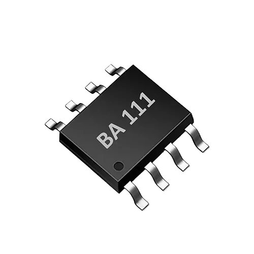
The BA111 is a single-channel TDS sensor interface ASIC for smart appliances, pet appliances and connected water-using equipment. It integrates bipolar probe drive and a UART control interface, enabling TDS and water temperature measurement with few external components. It suits products that require a compact solution and fast integration.
It must be stated clearly: the TDS reading provided by the BA111 is an engineering value for on-site screening, trend monitoring and automatic device control; it is not equivalent to a laboratory conductivity or total dissolved solids analysis result. If the end product needs to be used for regulatory compliance determination, standard methods should be used separately and a qualified laboratory report obtained.
2. How a TDS Sensor IC Works
A TDS sensor typically measures the conductivity of a water sample and then converts it to a TDS reading using an empirical coefficient. The BA111 uses bipolar probe drive, alternately reversing the excitation polarity to reduce the effect of probe surface polarization and scaling on long-term stability. Signal conditioning, temperature correction and digitization are performed inside the chip, and results are output via UART.
This type of solution is sensitive to changes in water quality, but is limited by probe constant, temperature compensation model and calibration. Engineering teams should treat it as a conductivity/TDS trend sensor, not as an absolute analytical instrument.
3. UART Command Control and Data Reading
The BA111 communicates with the host controller via UART. Before actual deployment, the command frame format, baud rate, data verification and response timeout must be confirmed from the official datasheet. The following are general integration steps and do not replace specific register descriptions.
3.1 Communication Parameter Verification
- Confirm that the UART level matches the MCU. If the MCU is a 3.3 V system, verify the BA111 I/O voltage tolerance and logic level; if they are not the same, add level shifting or select an appropriate supply.
- Confirm baud rate, stop bits and parity. Default values may differ by firmware version, so always refer to the datasheet.
3.2 Command Sequence
Typical flow: send measurement trigger command → wait for status word or busy flag → read TDS and water temperature data → verify CRC/checksum → parse and update the local buffer. If the chip supports continuous mode, pay attention to the data update rate and the MCU polling rhythm.
3.3 Error Handling
- Timeout: report an error after a limited number of retries.
- Verification failure: discard the current frame; a resend may be requested.
- Abnormal values: if the TDS reading exceeds the range or jumps, judge in combination with probe status, water quality and temperature.
4. Hardware Integration and Probe Wiring
The BA111 uses single-channel measurement with minimal external components. Probes are usually two-electrode or four-electrode structures, but specific models are not provided in this article. When wiring, note:
- Keep the connections between the bipolar drive terminals and the probe electrodes as short as possible to avoid parasitic capacitance and EMI interference.
- Ground the probe cable shield at a single point to avoid ground loops.
- Place supply decoupling close to the chip power pins; connect analog ground and digital ground at a single point to reduce crosstalk.
- If the probe is pluggable, keyed design and insulation treatment are needed to avoid damaging pins during live plugging and unplugging.
For specific pin functions, drive strength and sampling timing, refer to the datasheet and reference design.
5. Power Supply and Level Considerations
Smart appliances often use a 3.3 V host controller. If the BA111 UART pins are compatible with 3.3 V logic, they can be connected directly; otherwise, confirm the I/O voltage tolerance per the datasheet and add level shifting. After power-on reset, it is recommended to wait for initialization to complete before sending commands. Supply ripple should be kept within the range allowed by the datasheet; especially when the probe drive and digital circuits share a supply, add filter capacitors.
Do not directly apply a typical circuit without confirming the power supply parameters; different versions of the ASIC may have different requirements.
6. Difference Between On-Site Screening and Laboratory Analysis
| Dimension | On-site screening / trend monitoring | Laboratory analysis |
|---|---|---|
| Purpose | Equipment start/stop, filter reminder, water quality trends | Regulatory compliance, arbitration testing |
| Calibration | Periodic single-point or two-point calibration, relying on known conductivity standard solutions | Traceability to standard materials, per standard methods |
| Result expression | TDS or EC readings, convenient for device logic | Reported values, including uncertainty and method |
| Response time | Fast, suitable for online use | Slow, samples sent to a laboratory |
The BA111 suits the first-column scenarios. If wording such as “can replace laboratory testing” appears in product publicity, it is an incorrect statement and should be avoided.
7. Production-Line Test Focus Points
During mass production, a fast and reproducible verification process should be established:
- Communication self-check: after power-on, the MCU sends a query command to confirm that the BA111 returns model or version information (if supported); otherwise, it should at least be able to trigger measurement and receive a valid frame.
- Standard solution spot check: use a standard solution of known conductivity to verify that the reading is within the allowable deviation. The deviation range is determined by the product design and datasheet and should not be specified by this article.
- Temperature consistency: compare the water temperature reading with a reference thermometer to confirm that the temperature correction chain is normal.
- Insulation and leakage: check the insulation resistance of the probe interface to avoid reading drift caused by leakage in humid environments.
- Firmware records: record the firmware version, calibration data and test results of each station for traceability.
The goal of production-line testing is to reject abnormalities and early failures; it does not represent whole-product calibration. If the end product requires regulatory compliance, third-party testing must still be performed according to the relevant standards.
8. Limitations and Verification Methods
- Without knowledge of the specific UART command set, accuracy and temperature drift parameters, this article only provides integration methods.
- Bipolar drive can reduce polarization, but cannot completely eliminate probe contamination and aging.
- Temperature correction is based on the chip's internal model; deviations may increase under extreme temperatures or complex water quality.
- 0–3000 ppm is the product's nominal range; actual accuracy is affected by the probe, calibration and circuit design.
The following verification is recommended during development:
- Plot the actual reading curve using conductivity standard solutions at multiple levels, and record the non-linearity error.
- Conduct long-term immersion aging tests to observe reading drift.
- Perform high and low temperature tests to confirm the temperature compensation effect.
- Perform EMC testing to verify that UART communication is not falsely triggered under interference.
Frequently Asked Questions (FAQ)
Q: Can a TDS sensor IC like the BA111 replace laboratory testing? No. It is used for on-site screening and trend monitoring and is not suitable for regulatory determination. Laboratory analysis must be performed according to standard methods by a qualified laboratory.
Q: Where can the UART command set be obtained? You must consult the BA111 official datasheet or contact the original manufacturer's technical support. This article does not provide an unverified command table.
Q: Can a 3.3 V MCU be connected directly? The I/O levels and voltage tolerance in the BA111 datasheet need to be verified. If compatible, it can be connected directly; otherwise, level shifting is required. This article does not treat 3.3 V as a verified parameter.
Discuss your application
Tell us your target parameters, water matrix, interface and annual volume. Our engineering team will recommend a practical configuration.
Request a Quote