
# BA111 TDS Sensor IC Factory Calibration and Quality Inspection Process for Water Purification Equipment
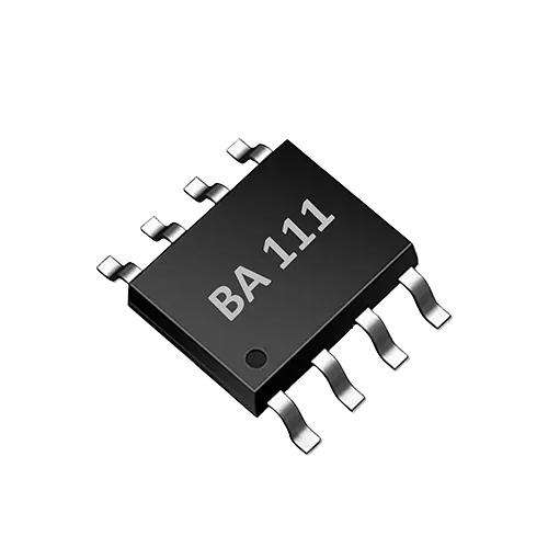
The TDS sensor IC performs the core tasks of conductivity measurement, temperature correction and digital output in water purification equipment. As a single-channel TDS sensor interface ASIC, BA111 offers a 0–3000 ppm TDS measurement range, bipolar probe drive, temperature correction and UART control, making it suitable for miniaturized water quality monitoring scenarios such as smart appliances. In mass production, OEMs cannot rely solely on the chip's factory parameters; they must establish a process covering probes, temperature, reference solutions, UART readings, calibration records, sampling inspection and the anomaly closed loop, so that every water purification device has consistent, traceable readings when it leaves the factory. This article is written from an engineering perspective and does not address regulatory laboratory certification.
Why do devices using a TDS sensor IC need factory calibration?
TDS measurement fundamentally depends on conductivity, and the probe constant, electrode material, temperature sensor position and assembly stress all change the measurement result. BA111 reduces probe polarization through bipolar drive and has built-in temperature correction, but the chip cannot perceive the individual differences of an external probe. Therefore, the complete device must be verified with reference solutions of known conductivity, and if the system design supports it, calibration coefficients can be written via UART commands. The goal of production-line calibration is to screen out units with excessive deviation and ensure batch consistency, not to replace laboratory analysis.
Two concepts must be distinguished: production-line calibration is a rapid consistency screening and belongs to trend monitoring; laboratory analysis follows the relevant standards and is issued under controlled conditions by a qualified body. The two should not be confused.
Minimum composition of the factory test system
A reliable BA111 production-line test station should include the following modules:
| Module | Function | Key requirement |
|---|---|---|
| Reference solution bath | Provides a liquid environment with a known conductivity/TDS value | Replace regularly to avoid cross-contamination; temperature controllable |
| Temperature reference | Provides a true water temperature baseline | Sufficient accuracy, compared with the BA111 temperature channel |
| UART reading tool | Sends commands and receives measurement results | Compatible with the BA111 control protocol, records raw readings |
| Calibration record system | Stores serial number, readings, environmental parameters and judgment results | Traceable, supports batch queries |
| Test fixture | Fixes the probe and temperature sensor to ensure consistent immersion depth | Avoids bubbles and flow disturbance |
Six-step factory test process
1. Power-on and UART communication self-check
After power-on, send a wake-up or read command via UART and confirm that the device returns a valid frame. Common criteria include stable response delay, correct frame checksum and no dropped frames during continuous reading. This step rules out poor soldering, cold joints, a chip that has not started or a firmware mismatch.
2. Probe and temperature sensor consistency check
Immerse the probe and temperature sensor in a constant-temperature reference solution according to the final structure and wait for thermal equilibrium. Read the BA111 temperature channel and compare it with the external temperature reference to confirm that the temperature deviation is within the process tolerance. For models with temperature correction, record the deviation for later judgment. An incorrectly positioned temperature sensor will cause subsequent temperature compensation to fail, so it should be exposed in this step.
3. Reference solution calibration verification
Select reference solutions covering the working range, for example low, medium and high conductivity points (the specific concentrations are determined by the product range; BA111 supports 0–3000 ppm TDS). Immerse the probe in each reference solution in turn and read the TDS reading output via UART. If a reading exceeds the deviation band, it is judged as an anomaly; for products that support coefficient writing, automatic calibration and re-testing can be performed. The deviation band should be set taking into account the uncertainty of the reference solution, probe batch dispersion and customer requirements.
4. Temperature compensation verification
Repeat the reading of a given reference solution point at at least two temperature points (for example 25°C and 40°C, according to the product specification) to confirm that the TDS result after temperature correction is stable. This step can reveal an incorrectly positioned temperature sensor or a compensation algorithm that is not active.
5. Repeatability and linearity sampling inspection
Perform multiple repeated measurements on the same probe and calculate the reading fluctuation; perform a linearity check on readings from multiple reference solution points to rule out electrode contamination, abnormal drive or ADC offset. The sampling ratio can be determined according to batch size and customer risk requirements.
6. Data recording and release
Write the serial number, raw UART readings, ambient temperature, reference solution lot number and judgment result of each device into the calibration record. Only devices that pass all criteria may be released. Records should be kept at least until the end of the product warranty period and support batch traceability.
Selection decision: why is BA111 suitable for water purification equipment production lines?
In mass production of smart appliances, an integrated TDS sensor IC has advantages over discrete op-amp solutions. BA111 provides single-channel measurement, bipolar drive and a UART digital interface, with simple peripheral circuitry; during production-line testing, raw measurement values can be read directly via UART, which facilitates automation. Temperature correction is built in, reducing the software burden on the host controller. These features make production-line calibration more standardized and also make it easier to read status during subsequent field maintenance.
Reference solution management and contamination control
Reference solutions should use certified reference materials and be replaced regularly to avoid cross-contamination from repeated immersion. Before testing, the probe should be rinsed with deionized water or the target water sample to prevent residue from affecting subsequent readings. The reference solution bath should have constant temperature or sufficient heat capacity to ensure thermal equilibrium before each test; avoid direct sunlight and drafts. The temperature reference sensor should be calibrated regularly and positioned close to the probe.
UART readings and automation integration
Production-line test software should automate the command sequence: read chip version, read temperature, read TDS, judge and record. Timeouts and retry mechanisms can be set to avoid misjudgment caused by occasional communication errors. Do not rely on a single reading; take the average of multiple readings to reduce noise.
Sampling inspection and anomaly closed loop
After the first article of a production run, a line change, a probe batch change or a reference solution change, the sampling frequency should be increased. Common anomalies include: overall reading offset, poor repeatability, temperature compensation failure and occasional UART frame drops. The anomaly handling process should form a closed loop:
| Anomaly symptom | Possible cause | Action |
|---|---|---|
| Overall reading too high/too low | Probe constant deviation, deteriorated reference solution | Replace the reference solution, check the probe, recalibrate |
| Poor repeatability | Probe contamination, bubbles, abnormal drive | Clean the probe, check the fixture, re-test |
| Temperature compensation failure | Incorrect temperature sensor position | Adjust assembly, verify the temperature channel |
| Occasional UART frame drops | Poor soldering, electromagnetic interference | Check soldering, shield the test environment |
Relying on single-point calibration alone is not recommended; at least two-point calibration helps reveal slope and intercept deviations. Reference solutions must have a traceable certificate and match the target TDS range.
Field application boundaries and limitations
The 0–3000 ppm TDS range of BA111 is suitable for trend monitoring in drinking water, water purifiers, pet water fountains, coffee machines and other smart appliances. It is not suitable for high-salinity industrial water, chemical oxygen demand surrogate measurement or trace heavy metal analysis. The data displayed by the device on site is used for screening and trend judgment and should not be used directly as a compliance report. In addition, probe life, scale and extreme temperature changes all affect long-term stability, so OEMs should recommend regular maintenance and verification in the product instructions.
FAQ
Q: How does BA111 work?
BA111 applies AC excitation to the probe through bipolar drive, measures the signal related to conductivity, and uses built-in temperature correction to convert conductivity into a TDS reading. The single-channel design simplifies peripheral circuitry, and the UART output is easy for the host controller to read.
Q: What is the difference between factory calibration and laboratory testing?
Factory calibration is production-line-level consistency screening, using reference solutions to verify whether the device meets process limits within its working range. Laboratory testing follows national or industry standards and issues a report from a qualified laboratory. The two have different purposes.
Q: Is the TDS sensor IC calibration permanently written into the chip?
It depends on the system design. BA111 outputs measurement values via UART; calibration coefficients can be stored in the host controller or the chip configuration can be adjusted by command. Production-line testing should at least verify whether the readings are within the acceptable deviation band.
Q: How should the production-line deviation band be set?
The deviation band should take into account the uncertainty of the reference solution, probe batch dispersion, temperature fluctuation and customer acceptance requirements. It is usually recommended to use statistical process control methods and periodically review control limits after accumulating actual data, rather than using fixed empirical values.
Discuss your application
Tell us your target parameters, water matrix, interface and annual volume. Our engineering team will recommend a practical configuration.
Request a Quote