
# Power Supply and Power Consumption Integration Considerations for the NSDD-Lite3
The NSDD-Lite3 is a compact multi-spectral water quality sensor that achieves online TOC, COD, UV254 and temperature measurement in a single probe. Its reagent-free, non-contact spectral design is suitable for embedding into industrial process water and smart appliance water systems. However, during system integration, power supply quality, power budget, control board layout and grounding directly affect measurement stability and long-term reliability. This article provides engineering implementation recommendations around DC 4.5–5.5 V supply, measurement current, control board design, grounding and startup commissioning.
Power Supply Design: Why DC 4.5–5.5 V Needs to Be Taken Seriously
NSDD-Lite3 integration recommends a stable DC 4.5–5.5 V power supply. This voltage range covers typical scenarios from USB 5 V to industrial power stepped down through an LDO, but a wide range does not mean power quality can be ignored. The sensor contains a spectral detection front end and digital processing circuits, which are sensitive to power supply ripple and transient drops.
Engineering issue: If a switching power supply is used directly and the output ripple is too large, it may cause spectral baseline drift, which in turn affects the stability of TOC/COD/UV254 readings. Therefore, two parameters need attention: ripple voltage and load regulation.
Decision method:
- Ripple is recommended to be kept within 50 mVpp (typical value; refer to the datasheet for specifics). If a switching power supply is used, add LC filtering near the sensor power input or use a low-noise LDO.
- Operating at 4.5 V reduces input voltage margin, so the LDO front-end dropout must be sufficient to avoid undervoltage reset caused by a sudden load increase.
Implementation steps:
- Determine the lowest voltage on the system bus (e.g., 5 V bus) and confirm it does not drop below 4.5 V at maximum load.
- Place 10 µF and 0.1 µF decoupling capacitors next to the sensor power pins, close to the connector.
- Use an oscilloscope to measure the voltage waveform at the sensor power pins and verify there is no drop during startup and measurement cycles.
Measurement Current and Power Budget
The measurement current of the NSDD-Lite3 depends on the operating mode: standby, communication and spectral measurement phases consume different amounts of power. During integration, do not estimate peak power consumption based only on average current, because instantaneous current may cause voltage drops.
Why actual measurement is needed: The datasheet provides typical values, but actual values are affected by communication rate, sampling frequency and ambient temperature. The control board power supply capability must cover the maximum peak current.
Power budget steps:
- Use a programmable electronic load or high-precision ammeter to measure current in different modes: standby current, continuous measurement current and communication burst current.
- Multiply the peak current by the supply voltage to obtain the maximum instantaneous power as the basis for selection.
- If the system is battery-powered, calculate the daily number of measurements and communication duration, estimate average power consumption, and ensure battery capacity and discharge rate meet requirements.
Note: Do not design based only on average current, because the sensor may briefly draw high current during spectral measurement; if the power supply transient response is insufficient, it will cause undervoltage restart.
Control Board Design Points
The NSDD-Lite3 offers UART or RS485 communication options; during integration, interface levels, isolation and wiring must be handled correctly.
Interface and levels:
- UART is 3.3 V/5 V TTL level (depending on model) and must match the host controller level. If the host controller is 3.3 V and the sensor is 5 V TTL, level shifting or voltage division is required.
- In RS485 mode, add termination resistors (120 Ω, only at the end of the line) on the A/B lines, and ensure common ground or use isolation.
Isolation protection: In industrial sites, it is recommended to add a digital isolator (such as the ADuM series) or optocoupler at the sensor communication end to prevent ground potential differences from damaging the device.
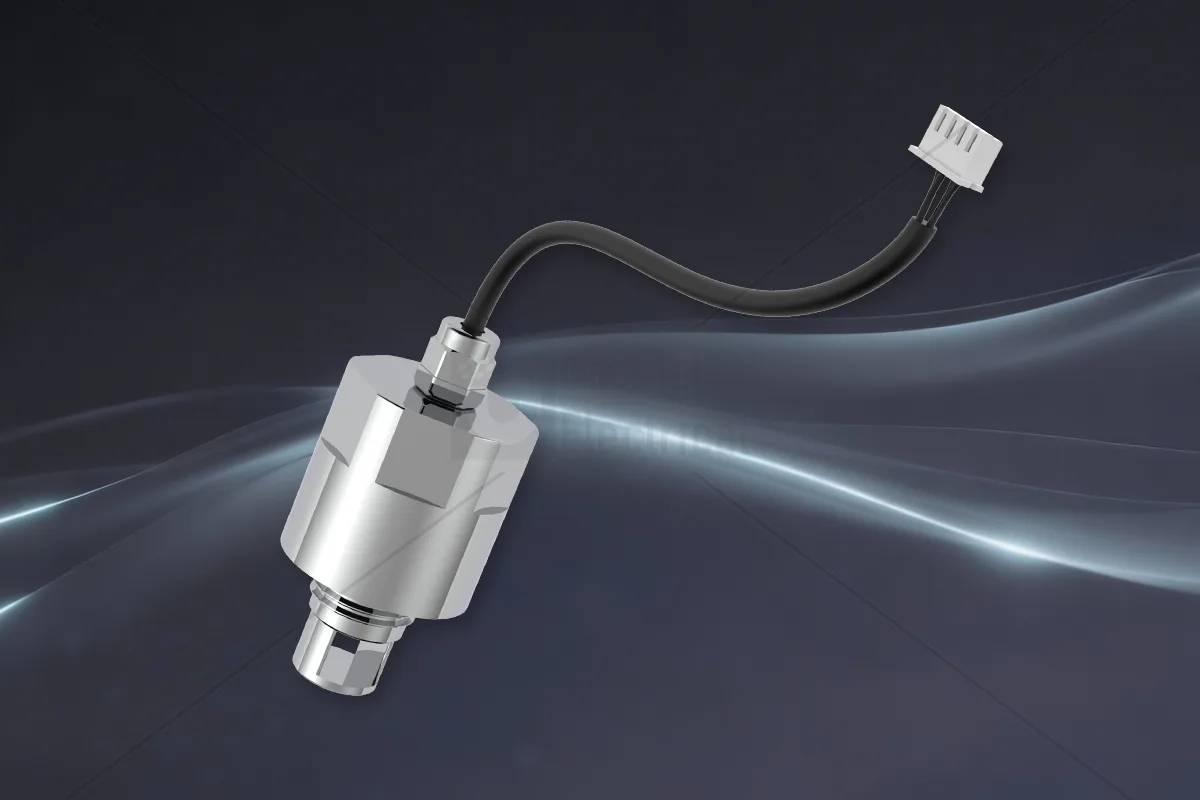
Wiring:
- Route power lines and signal lines separately to avoid parallel long-distance coupling interference.
- Keep sensor connection cables as short as possible; if long distance is necessary, use shielded twisted pair.
Grounding and Shielding: Reducing Noise Coupling
Poor grounding is a common cause of fluctuating readings in online water quality sensors. The NSDD-Lite3's 316L stainless steel housing is designed to contact the medium, but electrical grounding still needs careful handling.
Grounding strategy:
- Analog ground (AGND) and digital ground (DGND) should be joined at a single point to avoid digital switching noise entering the analog front end.
- The sensor metal housing is connected to the pipe through the mounting thread. If the pipe is well grounded, it can serve as shielding ground; if the pipe is insulated, a separate shield wire must be led out to the system ground.
- Do not connect the sensor housing directly to power ground unless the system has a clear equipotential design.
Shield wire handling: The communication cable shield should be grounded at one end (usually at the control cabinet end) to avoid ground loops.
Startup Commissioning Procedure
After completing hardware connections, it is recommended to start commissioning in the following steps:
- Pre-power check: Confirm power polarity is correct, voltage is within 4.5–5.5 V, and signal lines are not short-circuited.
- Power-on observation: On first power-up, measure the supply current and compare it with typical standby current. If abnormally large, disconnect power immediately and check.
- Communication test: Send a command to read device information and confirm UART/RS485 communication is normal.
- Measurement verification: Place the sensor in a known water sample (such as distilled water or standard solution) and observe whether TOC/COD/UV254 readings are within a reasonable range. Note: The sensor output is a spectrally converted value and requires on-site calibration or comparison with laboratory methods.
- Stability test: Run continuously for 24 hours and monitor reading drift and supply voltage changes.
Limitations and Verification Methods
The NSDD-Lite3 is an online spectral sensor used for rapid screening and trend monitoring. Its TOC/COD/UV254 readings are based on spectral models and are not regulatory-approved analytical results. In scenarios such as discharge compliance and drinking water safety, laboratory standard methods (such as the national standard potassium dichromate method for COD) must be used for periodic comparison and calibration.
Verification recommendations:
- Regularly check sensor response with standard solutions.
- Establish a correlation model with laboratory test results and evaluate deviations.
- Compliance reports cannot be issued based solely on sensor readings.
Frequently Asked Questions (FAQ)
Q: Can the NSDD-Lite3 be powered directly by USB 5 V? A: Yes, as long as the USB power supply ripple and voltage stability meet requirements. It is recommended to use a shielded USB cable and add decoupling capacitors at the sensor end. Note that the USB port has limited load capacity; if multiple devices share it, the total current must be calculated.
Q: Why does my NSDD-Lite3 reading occasionally fluctuate? A: Common causes include excessive power supply ripple, poor grounding and communication interference. Check the ripple at the power pins, ensure the shield is grounded at one end, and try lowering the communication baud rate.
Q: Can the NSDD-Lite3's COD measurement value be used directly for environmental reporting? A: No. Online sensors are used for trend monitoring and process control; compliance reporting must use laboratory standard methods. It is recommended to periodically calibrate the sensor model with laboratory data.
Q: What communication protocols does the sensor support? A: According to the materials, the NSDD-Lite3 supports UART or RS485 communication options. Please confirm the specific protocol frame format at the time of order and follow the datasheet.
Discuss your application
Tell us your target parameters, water matrix, interface and annual volume. Our engineering team will recommend a practical configuration.
Request a Quote