
# NSDD-Lite3 Pre-Pipe-Installation Engineering Checklist
In drinking water purification and industrial process water systems, the NSDD-Lite3 compact multi-spectral water quality sensor is used for online measurement of TOC, COD, UV254, and temperature. It uses a non-contact optical design, requires no chemical reagents, and outputs digital signals via UART or RS485. To obtain stable, representative readings, pre-installation engineering confirmation is more important than commissioning the sensor itself. The following checklist covers key items such as process connection, pressure, flow regime, bubbles, mounting orientation, power, maintenance space, and sampling ports.
1. Confirm G1/2 process connection and material compatibility
The NSDD-Lite3 uses a 316L stainless steel body and a G1/2 threaded process connection. Before installation, check:
- The mating port on the pipe or vessel should be G1/2 female thread (or a matching adapter), with thread specifications conforming to ISO 228 or equivalent standards. Avoid mixing in tapered threads such as NPT.
- Sealing method: O-rings or flat gaskets are typically used. Confirm that seal material is compatible with the medium (e.g., EPDM, FKM) to avoid swelling or extractables that could contaminate the process.
- Do not wrap threads with PTFE tape, because debris may enter the flow path; use a suitable sealing ring instead.
- Refer to the product manual for installation torque to avoid over-tightening that could damage threads or deform the stainless steel.
2. Verify the maximum 1.5 MPa pressure condition
The sensor can withstand a maximum working pressure of 1.5 MPa continuously. Before installation, verify:
- The system's normal operating pressure should be below 1.5 MPa, with a safety margin.
- Pay particular attention to transient pressure spikes caused by water hammer, pump start/stop, or rapid valve closure, which may exceed static pressure. Take measures to eliminate water hammer upstream or downstream of the sensor (e.g., accumulators, slow-closing valves).
- For special conditions such as high-pressure cleaning or steam sterilization, if 1.5 MPa may be exceeded, the sensor must be isolated or bypassed.
- During pressure testing, do not use the sensor as the sole pressure boundary; ensure the process connection is reliably sealed.
Include pressure checks in the table:
| Check item | Confirmation content | Acceptance criteria |
|---|---|---|
| Process connection | G1/2 thread matches, seals intact | No leakage, no cross-threading |
| Pressure boundary | System maximum pressure (including water hammer) | ≤1.5 MPa, with safety margin |
| Material | 316L stainless steel compatible with medium | No corrosion, no contamination risk |
3. Flow regime and bubble management
The NSDD-Lite3 is based on optical measurement; bubbles and particles can interfere with the light path and cause fluctuations in TOC, COD, and UV254 readings. The installation location should meet the following:
- The measurement window must be fully immersed in flowing water; avoid half-full pipe flow or empty pipe.
- Prefer vertical upward or inclined installation so that bubbles can easily rise and escape rather than accumulate at the window.
- If installing in a horizontal pipe, mount the sensor on the side or bottom of the pipe. Top mounting is usually avoided to prevent bubble accumulation; bottom mounting is avoided to prevent sediment from blocking the window. However, refer to the product manual for specifics.
- There should be sufficient straight pipe upstream of the sensor to avoid vortices and bubbles caused by elbows, valves, or pump outlets. The specific straight pipe length is not provided; numerical values are not recommended.
- For media prone to bubble formation (e.g., dissolved air water, heated water), install a degassing device or vent valve upstream of the sensor.
- Flow velocity should be stable and sufficient to carry away bubbles, but not so high as to cause erosion or cavitation. The specific flow velocity range is not provided; consult the product datasheet.
4. Mounting orientation and optical window protection
The non-contact optical components are inside the sensor, but the measurement window surface must remain clean. Mounting orientation directly affects contamination deposition:
- Avoid installing the sensor at the lowest point of the pipe to prevent sediment, rust, and other deposits from covering the window.
- If the medium contains suspended solids, consider installing a filter before the window or selecting a self-cleaning solution, but evaluate pressure loss.
- After installation, ensure the window is oriented parallel to or at an angle to the water flow to reduce direct impact and particle accumulation.
- For long-term operation, inspect the window surface for scaling, biofilm, or oil films during maintenance.
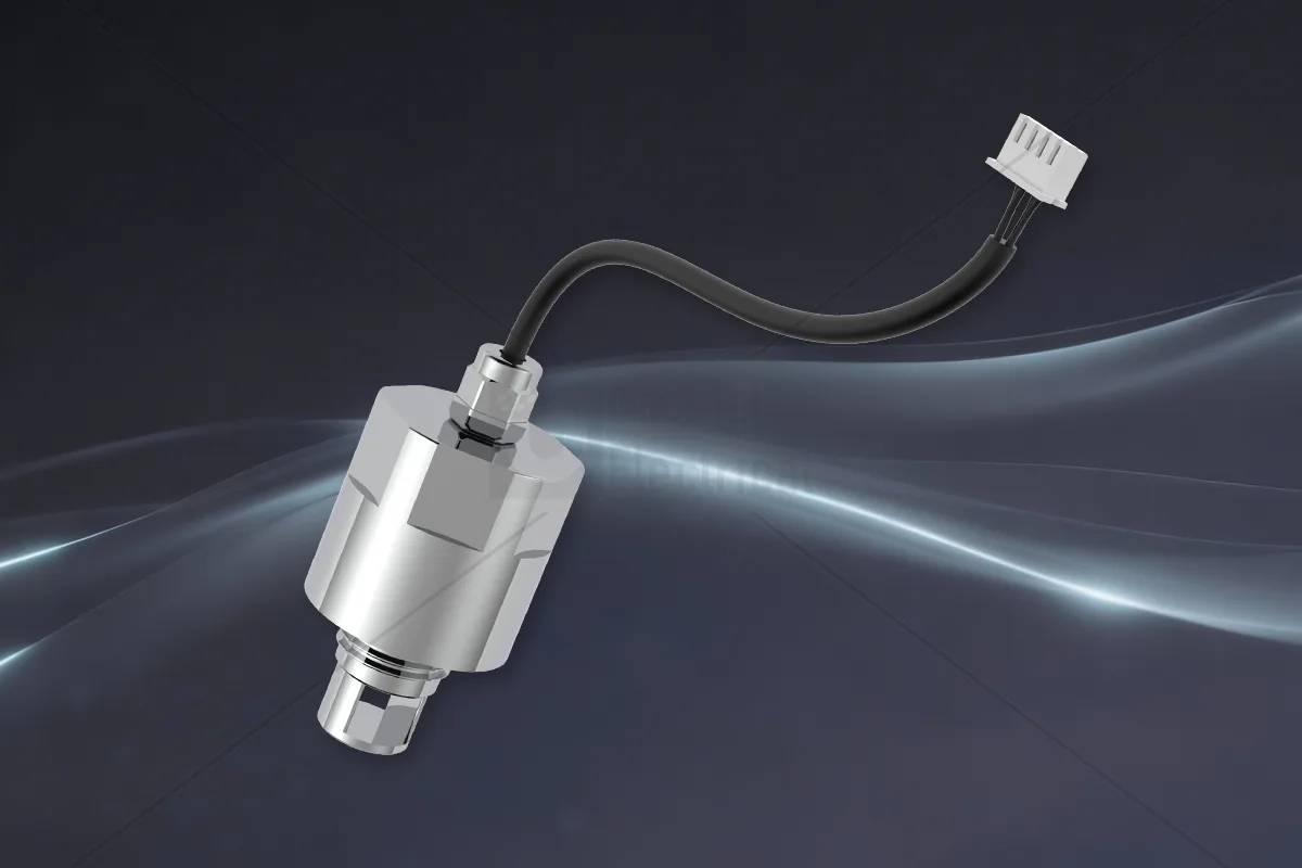
5. Power and communication checks
The NSDD-Lite3 supports UART or RS485 communication. Before installation, confirm:
- Supply voltage, polarity, and power match the product specifications (refer to the datasheet for specific values; not provided in this database). Do not use an unregulated power supply.
- RS485 wiring should use shielded twisted pair, with the shield grounded at one point, and avoid running parallel to power cables.
- Termination and bias resistors should be configured according to the network topology to ensure bus impedance matching.
- The sensor and receiving device (PLC, gateway, controller) must be common-grounded or isolated to prevent ground loop interference.
- If using UART, pay attention to level matching (TTL or RS232) to avoid damaging the interface by direct connection.
6. Maintenance space and sampling port setup
To facilitate calibration, cleaning, and verification, reserve the following during installation:
- Leave at least one sensor length of removal space around the sensor for unscrewing or pulling out.
- Install a sampling valve or bypass sampling port near the sensor for collecting water samples for laboratory analysis and comparison with online readings.
- If using a flow-through cell installation, design a bypass branch to ensure the sensor can be inserted or removed online without interrupting the main process.
- The sampling port should be as close as possible to the sensor to avoid water quality changes from long-distance pipe transport.
7. Applicable boundaries and verification of online monitoring
It must be clear: the NSDD-Lite3 provides rapid, continuous online trend monitoring and cannot replace laboratory standard methods (such as HJ 828 dichromate method for COD, or combustion oxidation method for TOC). There may be systematic bias between the two, depending on water composition, turbidity, color, etc.
- For the first startup after installation, run continuously for at least 24 hours to observe reading stability.
- When sensor readings are stable, simultaneously collect water samples for laboratory analysis using standard methods to establish a correlation between online readings and laboratory values.
- Perform comparisons periodically (e.g., monthly or quarterly) and adjust correction factors or calibration curves based on deviations.
- If the water composition changes significantly (e.g., water source switching, process adjustments), re-establish the correlation.
Frequently Asked Questions (FAQ)
Q: Can the NSDD-Lite3's G1/2 connection be directly installed on a metal pipe? A: Yes, as long as a G1/2 female threaded port is reserved on the pipe and suitable seals are used. If there is a galvanic corrosion risk between the pipe material and 316L stainless steel, insulation measures must be taken.
Q: Does the maximum 1.5 MPa pressure include temperature compensation? A: 1.5 MPa is the long-term working pressure that the sensor structure can withstand, independent of temperature measurement. However, at high temperatures, the pressure-bearing capacity of seals and materials may decrease; refer to the temperature-pressure curve in the product manual (if available).
Q: How much difference between online COD readings and laboratory COD values is normal? A: There is no fixed value. It can range from a few percent to several tens of percent, affected by water composition, interfering substances, and sensor calibration model. On-site comparison must determine the acceptable deviation, and it should be used for trend monitoring, not directly as compliance data.
Q: Why do bubbles have a large impact on UV254 and COD measurement? A: Bubbles scatter and reflect light, changing the effective optical path length and causing signal noise. Therefore, during installation, avoid bubble accumulation and degas if necessary.
The above are the core pre-pipe-installation engineering check items for the NSDD-Lite3. By confirming each item, you can reduce installation rework risk and improve the reliability and maintainability of online water quality sensor data.
Discuss your application
Tell us your target parameters, water matrix, interface and annual volume. Our engineering team will recommend a practical configuration.
Request a Quote